Polygon / Hotspot Tool
![]() The Polygon / Hotspot Tool can be used to create many different types of free-form shapes. The Polygon also has the ability to display a background image, and can be configured to shape itself to match the contents of an image. A Polygon can be created manually using the mouse or automatically by importing an image file.
The Polygon / Hotspot Tool can be used to create many different types of free-form shapes. The Polygon also has the ability to display a background image, and can be configured to shape itself to match the contents of an image. A Polygon can be created manually using the mouse or automatically by importing an image file.
To manually construct a Polygon using the mouse, first select the Polygon/Hotspot icon from the Tool Palette. Move the mouse cursor to a point in the publication workspace where you want your Polygon to start. Hold down the left mouse button and drag to draw a line for the first side. When the line reaches the desired length and position, release the mouse button. Next, move the mouse to the point where the second side will terminate. A rubberband line will follow the cursor. When the second side has been correctly positioned, click once with the left mouse button to set the line. Repeat this step to construct the rest of your shape. (A Polygon must have at least three sides.)
To complete the Polygon, click on the point at which you started. You also can complete the Polygon by clicking the right mouse button anywhere on the page and VisualNEO Win will connect the last line to the first automatically.
After defining the initial shape, the Polygon will appear on the screen. When the Polygon object is selected, small boxlike handles will be added to the endpoint of each line. At this point, you can make changes to the polygon's shape.
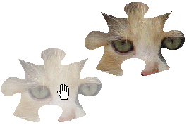
To reposition one of the endpoints, place the mouse cursor over the endpoint's handle. (The cursor will include a directional arrow ![]() when it’s in the correct position.) Hold down the left mouse button and drag the handle. As you move, the shape will stretch or shrink. When you are satisfied with the shape, release the mouse button.
when it’s in the correct position.) Hold down the left mouse button and drag the handle. As you move, the shape will stretch or shrink. When you are satisfied with the shape, release the mouse button.
Should you need to add another endpoint, position the mouse cursor over the point on the outline where you would like a new handle and click the left mouse button. (The cursor will include a plus sign ![]() when it passes over a location where a new handle can be added.)
when it passes over a location where a new handle can be added.)
To delete a handle, position the mouse cursor over the unwanted handle. (The cursor will include a directional arrow ![]() when it is in the correct position.) Hold down the Ctrl key, click the left mouse button and the handle will disappear.
when it is in the correct position.) Hold down the Ctrl key, click the left mouse button and the handle will disappear.
To create a Polygon using an image file, first select the Polygon/Hotspot icon from the Tool Palette. Move the mouse cursor to a point in the publication workspace where you want your Polygon to appear. Click and release the left mouse button once. A Windows File Selector will appear, allowing you to select an image file. Once you select a file, VisualNEO Win will attempt to convert the image into a Polygon shape.
When converting an image into a Polygon, VisualNEO Win expects the image to conform to some specific guidelines. During the conversion, VisualNEO Win uses the image’s transparent color as a guide to determine the Polygon’s outline. By default, VisualNEO Win assumes that the transparent color matches the pixel in the image’s lower left corner. (If needed, you can specify a different transparent color from the Polygon/Hotspot Properties screen.)
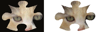
When creating images for use with the Polygon object, it should be clear which portions of the image are to be transparent. In the example below, black is the transparent color for the original image on the left. When imported into VisualNEO Win, the black portion of the image is trimmed off resulting in the clean Polygon shape below:
|
|
|
|
Original Image |
Polygon |
Once created, you can modify the Polygon’s properties by right clicking on the object. The Polygon/Hotspot Properties screen will be displayed, allowing you to modify the object’s appearance and behavior.
The Polygon/Hotspot Properties screen is divided into three sections indicated by the icon images on the left: General, Drag & Drop and Actions. To view the settings for a section, click the corresponding icon.
General
The Background Image field contains the name of the file displayed inside the Polygon. Even though you’ve imported the file into your publication, it’s still an external file. Edit the file outside of VisualNEO Win and changes will appear in your publication. The file will be bound inside the publication only during the Compile stage. To the right of the field are three small buttons: click the ![]() button to select a different file. Experienced authors can use the
button to select a different file. Experienced authors can use the ![]() button to perform advanced file options or the
button to perform advanced file options or the ![]() button to replace the file name with a variable.
button to replace the file name with a variable.
You can designate a portion of the image as transparent by clicking the small arrow button next to the Transparent color box. VisualNEO Win will prompt you to select a color to serve as the transparent portion of the image. The background will show through pixels in the image matching this color.
If the Use transparent portion of image to define polygon option is enabled, the transparent color will be used to determine the Polygon’s shape as described in the previous section. When this option is disabled, the Polygon’s shape must be defined manually.
Move the Opacity slider to the left to allow a portion of the background to show through the image. The further to the left you move the slider, the more background will be visible. This is often called an alpha channel transparency effect. To display the image in its normal solid form, move the slider all the way to the right. The opacity option is only available in 16 million color modes.
The Polygon object can be configured to support drag and drop functions, allowing readers of your publication to move the object using the mouse. Drag and drop modes include None, Manual and Automatic.
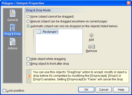
When None is selected, the object cannot be dragged. Manual allows the object to be dragged anywhere on the page. Automatic allows you to specify other objects to serve as drop targets. When using automatic mode, VisualNEO Win will only allow the dragged Polygon to be dropped on top of objects that appear in the drop target list. You can modify the behavior of both of these modes using the “Drag Drop” Action described below.
During drag and drop operations, VisualNEO Win doesn’t actually move the object. Instead, a semitransparent ghost image representing the object follows the reader’s mouse cursor around the screen. The original object remains visible during this process, unless you enable the Hide object while dragging option.
Enabling the Bring object to front after drop option will insure that the dragged object doesn’t end up underneath the object it’s dropped on.
Actions
Polygons support the following Action Events: Click, Right Click, Mouse Enter, Mouse Exit and Drag Drop. Click the appropriate tab at the bottom of the Action Editor to create or edit Actions for the events you want to control.
If you’ve enabled either the Manual or Automatic Drag and Drop Modes above, you can use the special “Drag Drop” Action to control exactly what happens at the end of the drag and drop operation. VisualNEO Win triggers the Drag Drop Action when the object is dropped. If you do nothing, VisualNEO Win will move the object to the new location provided the specified Drag Mode criteria has been met. However, just before the Drag Drop Action executes, VisualNEO Win will initialize the following special variables which can be used to influence how the drop operation is completed:
|
[DropAccept] |
Setting this variable to “False” will cancel the drop operation. For example: SetVar "[DropAccept]" "False" Also, if you specified a drop target for this operation (Automatic mode), you can override that and allow the object to be dropped anywhere by setting this variable to “True”. (See the SetVar Action for information on how to set variables.) |
|
[DropX], [DropY] |
This is the proposed new location for the dropped object. You can change these coordinates to affect where the object is placed. |
|
[DropTarget] |
If the drop occurred on top of one of your specified drop targets, this variable will contain that object’s name. |
Note: For basic drag and drop operations, you do not need to worry about these variables or place any code in the Drag Drop Action.
See Understanding Actions and Variables and Action Command Reference for a complete discussion of the Action Editor and Action Commands.